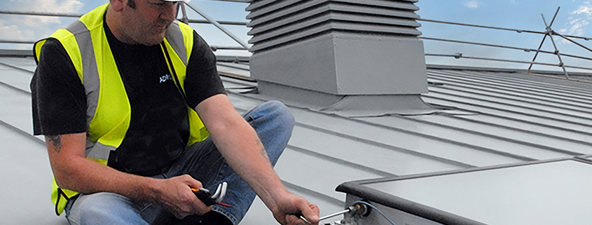
This week we take a look at commercial solar thermal for installers, the advantages and the requirements for delivering a proven sustainable technology as part of a water heating system.
For commercial buildings sustainability undeniably comes at a cost, and water heating remains a major source of energy demand, accounting for up to 30% of daily power consumption for some organisations. It is also often a business-critical need, so addressing the demand should be an early function of any sustainability strategy. Commercial hot water systems are inherently complex, increasingly so as the industry moves from gas-fired systems to electric, but there remains one proven, relatively simple renewable technology that has clear advantages.
Capable of offsetting at least 30% of the annual energy demands for water heating, commercial solar thermal systems are ideal for organisations which rely on large amounts of domestic hot water (DHW). For existing buildings with gas-fired water heating solar thermal is employed as a system pre-heat, reducing demands for gas to actively cut carbon emissions from the buildings. For new builds or major refurbishments, however, we are seeing the shift to direct electric, where solar thermal acts as either a pre-heat for an electric boiler system or is deployed as a mid-heat to take full advantage of an air source heat pump’s capability to optimise the generation of pre-heat from the cold feed.
Demand for these systems is on the increase, but as with other renewables, there remains a need for skilled installers to meet this new demand. Modular, high-performance flat plate collectors, combined with drain back vessels are by far the most efficient way to heat water with solar energy. The drain-back provides overheat protection of the solar fluid (glycol) used in transferring heat energy from the collector to the system’s hot water cylinder. For those familiar with commercial plumbing, there is a clear opportunity to upskill and add the technology to their range of services.
Planning is key for solar thermal installations. Because drain-back technology relies on gravity, all vessels in an array must be level with a maximum pitch of 0-1 cm over the total length of the drain-back assembly. This avoids the river effect in the pipework. Also, the solar collectors must be sited a minimum of 50 cm above the top coil connection to the system cylinder. This means solar thermal systems will need to be situated on the roof or façade of a building and will be problematic for buildings designed with rooftop plant rooms.
There are a variety of options available when installing collectors with drain-back. They can be built on or into the roof, mounted on the building’s façade, or erected on an A-frame on flat or pitched roofs, or on a wall. The ideal facing direction to maximise insolation is south with a 36° pitch. Collector mounting, pitch and direction are set by the building, and an East/West split will demand two coils since the drain-back vessels will not be level. Built-on/built-in arrangements will support a single or double array of collectors, a flat roof gives the option of many more.
The other major consideration when installing collectors is the wind loading affected by altitude, height, topography, and layout of adjacent structures. Collectors which are built on or in the roof will be bolted into position, but for A-frame installations extra care needs to be taken since wind loading will be significantly higher for a vertical install versus a horizontal collector installation (30° angled frame). Wind loadings, which include a 50% safety factor, are defined by horizontal forces in kN and maximum pull-off. The manufacturer’s calculation will indicate extra ballast weight required, usually in the form of a concrete block. In locations where high winds are expected, it is also advised to provide mechanical fixing in the form of guy wires, or a Unistrut run-through and connected to the A-frame and fixed to a weathered-in post installed into the roof.
The collector is essentially ‘the boiler’ so flow and return are set in relation to the collector. The collector incorporates a copper meander, flowing in one side and out the other for natural balance. The flow from the collectors enters the top of the drain back vessel and passes from the bottom of the vessel to the coil top connection. Ideally, the flow and return will be at opposite ends of the collector array, however, up to six collectors can be arranged with same-side connections. Solar thermal piping and joining employ 22mm or 28mm plumbing in either copper or Solarflex, with copper preferred for all horizontal runs. Solar systems are however too hot for soft solder, so joints should use compression (brass olive), solar press fit, silver solder or braze.
For installers considering adding solar thermal to their portfolio, while you do not need to be a specialist, it really helps to understand the limitations before you begin. In our experience it is easy for errors to creep in, so Adveco offers free CPD sessions on solar design that can be adjusted to focus on the installation process. For a small fee, our engineers will come to site and walk through the first installation with your team. It’s a sensible investment that guarantees a smooth commissioning process on a first install

